venturi flow meter formula
Use this calculator to quickly calculate the actual flow rate through the Venturi tube flow meter with only a few inputs. The pressure difference between them.

Venturi Meter Engineeringclicks
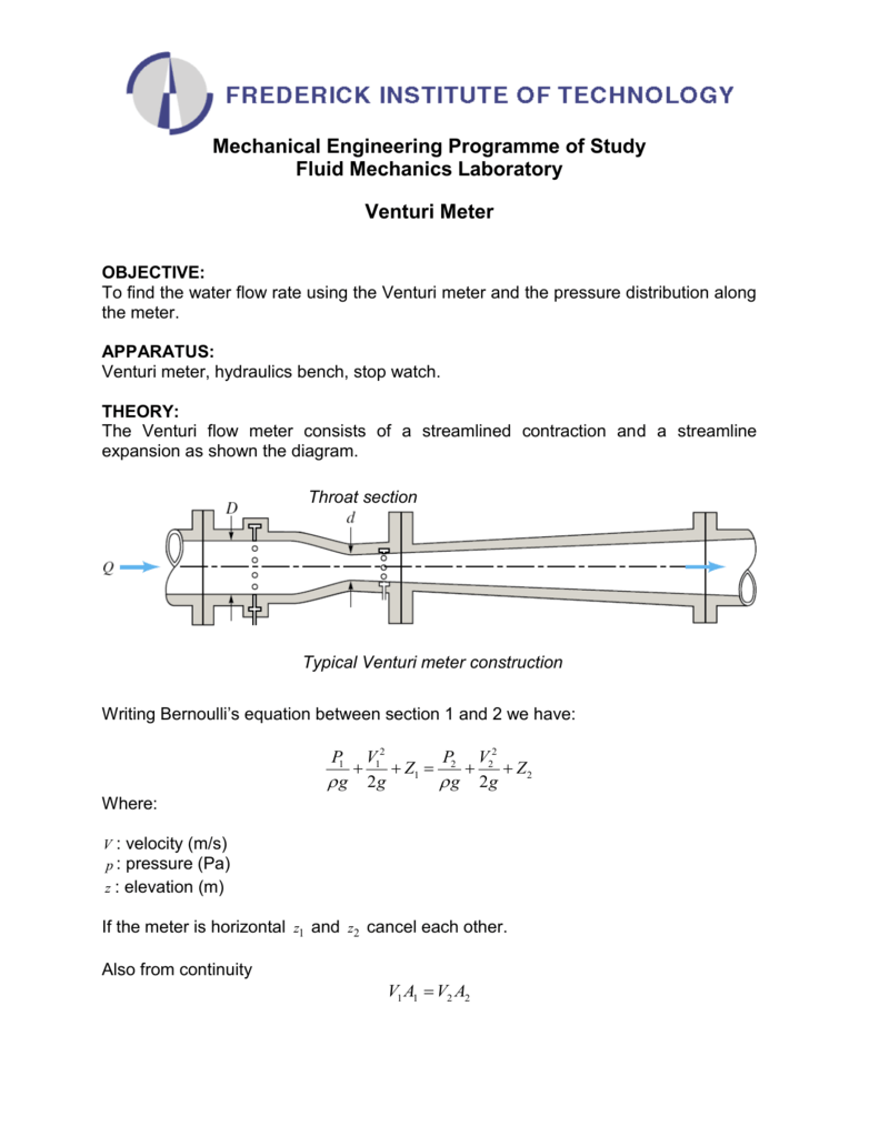
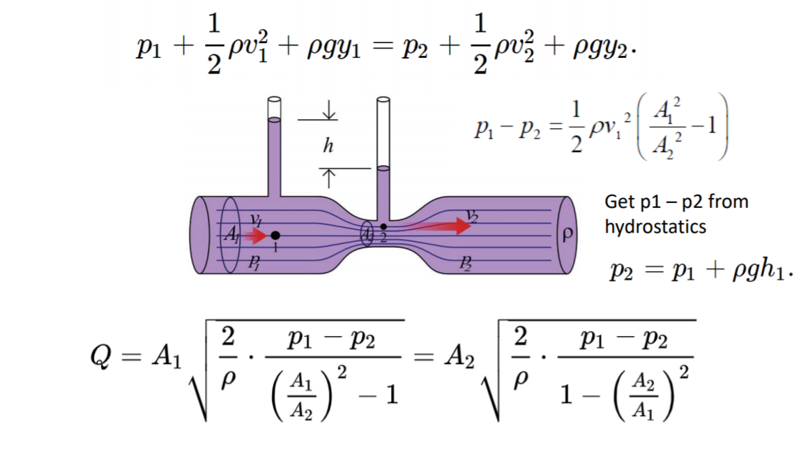
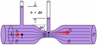
P1 12 ρ v12 γ h1 p2 12 ρ v22 γ h2 1b where γ specific weight of fluid kgm3 slugsft3 h elevation m ft Assuming uniform velocity profiles in the upstream and downstream flow - the Continuity Equation can be expressed as.
. 7 Venturi meter or venturi tube derivation discharge. Fluid flows through this tube hence the volume. V flow velocity ms fts The equation can be adapted to vertical flow by adding elevation heights.
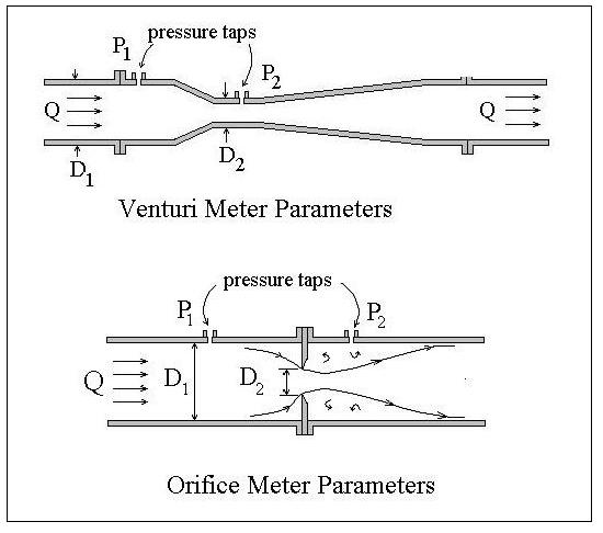
Error Messages given by Venturi Calculation Top of Page All inputs must be positive. Venturi meters are flow measurement instruments which use a converging section of pipe to give an increase in the flow velocity and a corresponding pressure drop from which the flowrate can be deduced. In general actual discharge is always less than Theoretical Discharge.
Where C v is the Venturi coefficient A 1 and A 2 are the areas of the pipe cross-section ΔP is the difference between the pressure in A 1 and A 2 and ρair us the density of air. C Venturi meter Where 136 Specific gravity of mercury and ω Specific weight of the oil By applying Bernoullis equation at sections 1 and 2 we can get As the pipe is horizontal hence z1 z2 But p1-p2ρg is the difference of pressure heads at sections 1 and 2 and it is equal to h or p1-p2ρg h. Where a b c d.
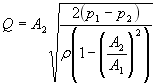
C d Q act Q As Q actual will always be less than Q theoretical due to frictional losses the value of C d is always less than 10. As the fluid enters the converging section its velocity begins to increase reaching a maximum value. According to the formula the flow rate can be calculated according to the following formula.
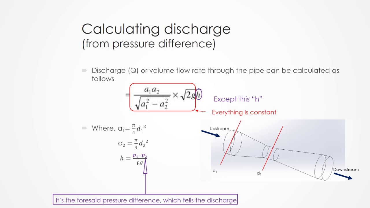
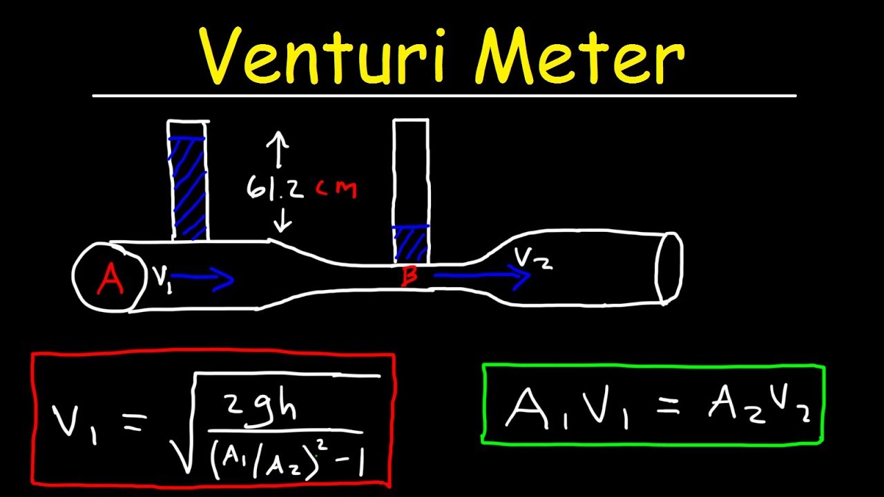
We get the following a1 and v1 are the area and velocity of point 1. This calculator performs the flow rate calculation from the measured pressure difference caused by the flow contraction in the throat of the Venturi tube. From the continuity equation at sections 1 and 2 we get This expression is the Theoretical Discharge of Venturi Meter.
This is an initial check of user input. A Venturi meter filled with mercury is placed in the pipe as shown in the figure. Theoretical discharge -venturimeter is simply the rate of flow of a liquid through a venturimeter channel and is represented as q a1a2 sqrt2gh sqrt a1 2- a2 2 or rate of flow area of cross section at the inletarea of cross section at the throat sqrt2acceleration due to gravityventuri head sqrt area of.
If D2 D1 you get the square root of a negative number but neither condition applies to a venturi. A2 and v2 are the area and velocity of point 2. Note that if D2 D1 then β 1 and Q is undefined.
So the venturi meter discharge coefficient is given by. The venturi flow meter is installed as a section of pipe or tubing and is used to measure the flow of fluids either gaseous or liquid. To find the Coefficient of discharge then we have to divide actual discharge by the theoretical discharge.
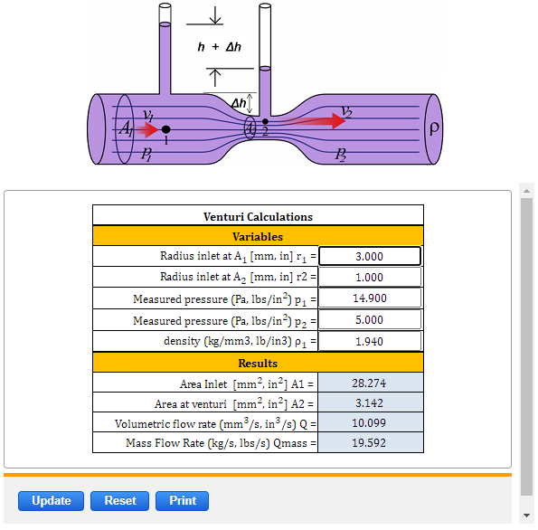
Subscript 1 refers to entering conditions. Venturi meter Length of the venturi meter 16mm Entrance diameter D 1 16mm Throat diameter D 2 7mm Length 8mm Cross-sectional area of the throat S 2 π D 2 24 β D 2D 1 Collector Tank Readings Manometer Reading Coefficient of discharge é Initial water level cm Final water level cm Time taken sec Flow rate Q m3sec h 1. Q volumetric flow rate m 3 s in 3 s Q mass Mass flowrate kgs lbss A 1 area Π r 2 mm 2 in 2 A 2 area Π r 2 mm 2 in 2 r 1 radius inlet at A 1 mm in r 2 radius inlet at A 2 mm in p 1 Measured pressure Pa lbin 2 p 2 Measured pressure Pa lbin 2 ρ density kgm 3 lbin 3.
C a b log Re c log Re 2 d log Re 3. The length of the convergent cone of a venturi meter is found with formula D-d where D Diameter of inlet section and d diameter of the throat. The volumetric flow rate through the pipe is Q 5 10-3 m 3 s.
A1 is cross sectional area of first part of the tube Pi R2 0000415 M2 A2 Pi R2 00000283 M2 P Density of air 1225 P1-P2 DeltaP 2222 Pa. The number of constants was set equal to the number of data points plus 1. The classical Venturi meter whose use is described in ISO.
The speed of water in both cross sectional areas of the pipe. The meter consists of a converging inlet section a short straight throat section and a diverging section. What is the included angle of a venturi meters divergent cone.
Figure 1 Herschel-Type Venturi Meter - Typical. The mass flowrate can be found by multiplying Q with the fluid density Glossary. The difference in height h of mercury on the two sides of the U-tube.
As pipe is horizontal Z1 Z2 Where h p1-p2ρg difference of pressure heads at sections 1 and 2. The discharge coefficient C is a constant value for given venturi dimensions. Flow Rate Q meter3second cchour centimeter3second centimeter3hour deciliterminute foot3minute foot3second gallonminute literday literminute litersecond meter3day meter3minute milliliterhour milliliterminute.
They have been in common use for many years especially in the water supply industry. The coefficient of discharge for Venturimeter Cd is defined as the ratio of the actual flow rate through the venturi meter tube to the theoretical flow rate. Area a2 is smaller than area a1.
DD must be 1. If we want to find actual discharge then we will multiply the coefficient of discharge into the theoretical discharge. I am using Bernoulli Equation of the Venturi meter as above From my MPX5010 DP Sensor I am getting a pressure differential of 2222 pa.
Based on the conditions of the experiment C v equals 08159. A discharge coefficient C is typically introduced to account for the viscosity of fluids C is found to depend on the Reynolds Number of the flow and usually lies between 090 and 098 for smoothly tapering venturis. Subscript 2 refers to throat conditions.
The coefficient C must be adjuste to accommodate variations in water temperature. P1 absolute pressure lbf ft 2 p2 gauge pressure lbf ft 2 β ratio of diameters D2D1 for venturi and sharp-edge orifice and d D for flow nozzle D pipe diameter d throat diameter Note. The ideal gas law in the form ρ MWPRT can be used for this purpose.
When the fluid whose flow is being measured by an orifice flow nozzle or venturi meter is a gas the density is a function of both temperature and pressure so a means of determining the density of the gas at the pipeline temperature and pressure is needed.
Orifice And Venturi Flow Meter Calculations Spreadsheet Low Cost Easy To Use Spreadsheets For Engineering Calculations Available At Engineering Excel Spreadsheetslow Cost Easy To Use Spreadsheets For Engineering Calculations Available At
Venturi Meter Finding Pressure Difference Physics Forums

Flowrate Calculation For A Venturi
Venturimeter Pressure Gauges Tells The Rate Of Flow Youtube
Venturi Meter

Venturi Meter Definition Parts Working Derivation Applications Pdf
Solved A Formula Is Given For The Volumetric Flow Rate Chegg Com

Flowrate Calculation For A Venturi
Venturi Meter Problems Bernolli S Principle Equation Of Continuity Fluid Dynamics Youtube
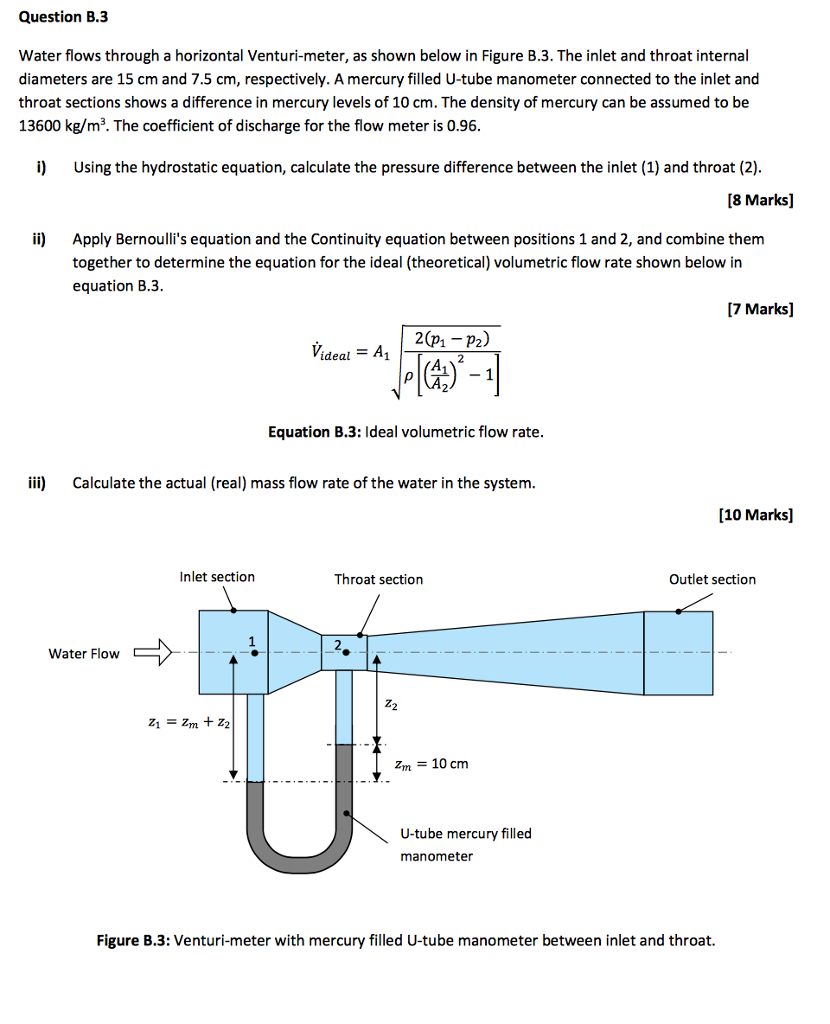
Solved Water Flows Through A Horizontal Venturi Meter As Chegg Com

Venturi Meter Youtube
Venturi Flow Equation And Calculator
No Title
Venturi Flow Equation And Calculator
Orifice Nozzle And Venturi Flow Rate Meters
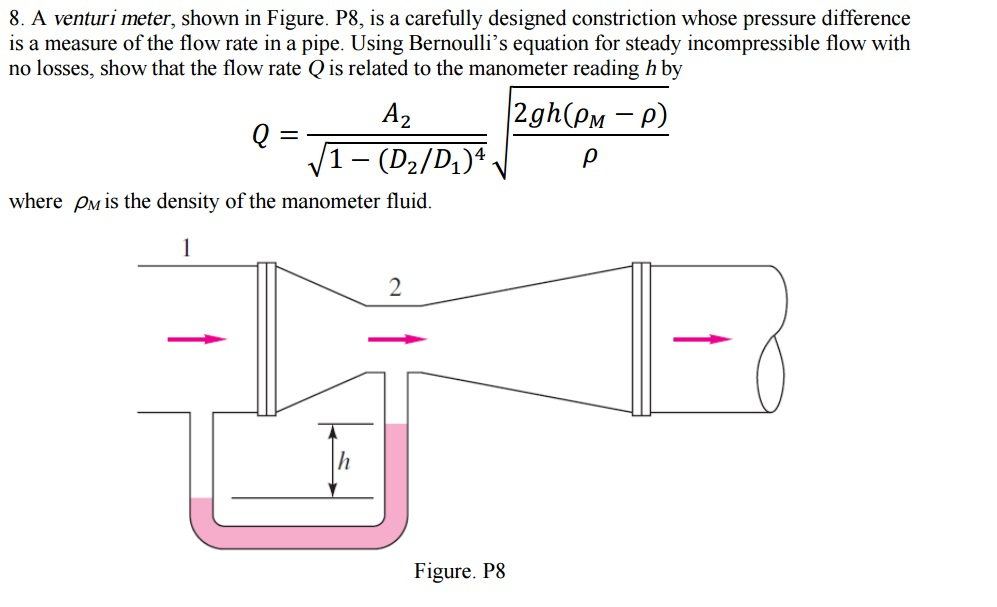
Solved A Venturi Meter Shown In Figure P8 Is A Carefully Chegg Com
Venturi Meter Design Equations Formulas Calculator Flow Rate

Theoretical Fluid Mechanics Venturi Meter Mike Soltys Ph D
Venturi Meter